- Category
- What's New?
- FightSticks/Pads
- Joysticks
- Pushbuttons
- Spare Parts & Tools
- Hardware & PCB
- Electrical
- Customize
- Merchandise
- Sales & Clearance
- Brand
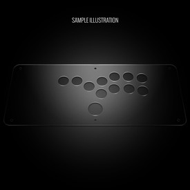
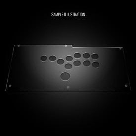
Blank Plexi Cover for Venom (PS4)/Mayflash F500 Universal Stickless
Choose Your Options
-
Product Description
Please Read Before You Order
Below is important information to know before placing a custom order with us:
- Project L Official Artwork: Do not submit the PNG samples. Instead, please download the zipped Photoshop PSD version, unzip the file and integrate them into our artwork templates
 for your desired fightstick model
 - Custom Orders do Not Ship Separately: If you place an order for a personalized product along with non-custom products, such as arcade part or merchandise, please note that all items will ship together.
Metal Conversion Panel Replacement and Plexi Replacement Required for this Layout
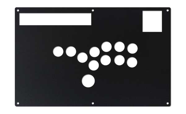
 The original metal panel was not designed to accomodate this button layout; it requires a metal conversion panel. Additionally, artwork for this Fightstick requires a plexiglass replacement. If you have not yet purchased, consider one of our discounted conversion bundles, which is available for this model. These are compatible ONLY with AFS metal panels, and may not work with metal panels from other vendors.
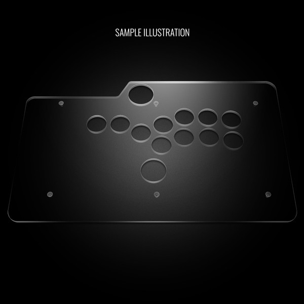
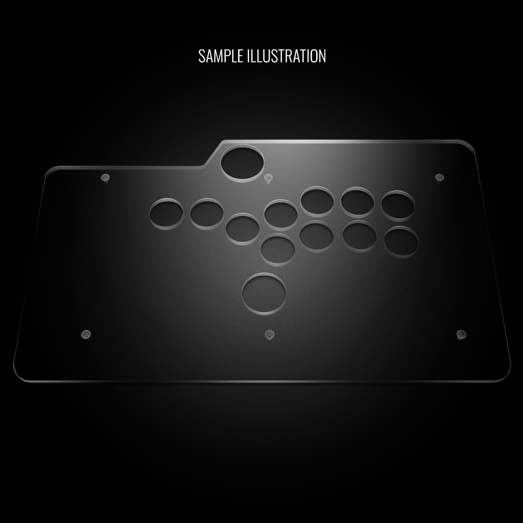
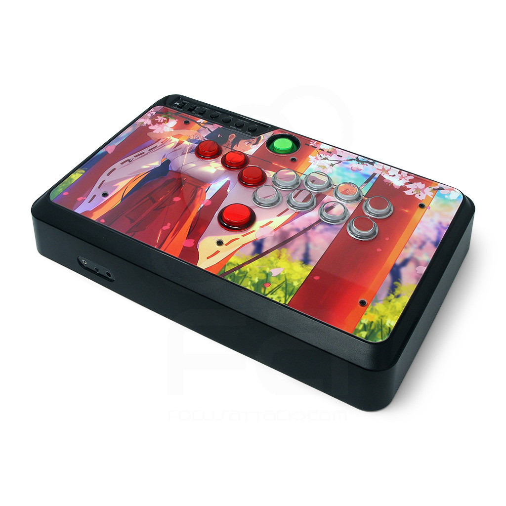
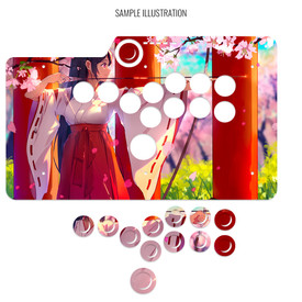
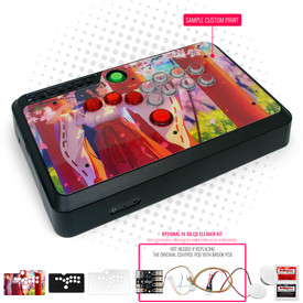
The art cover replacement top panel offers one of the best ways to customize your joystick. The plexiglass sits atop specially cut artwork, allowing you to add or replace new custom artwork to match your joystick theme.
Designed for Venom PS4, MAYFLASH F500/Elite (PS4/PS3/XB1/XB360) with AFS Stickless Conversion Metal Plate Replacement
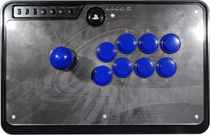
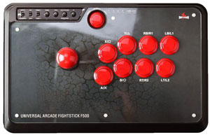
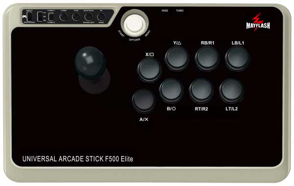
Venom PS4/Mayflash F500/Elite Stickless Panel Template
Will also fit 8BitDo FC30 and Mayflash XB360/PS3/PC. Not compatible with smaller Mayflash F300, Venom multi-console, or 8bitdo NS300 model (2Mb zip)The Stickless Mayflash requires the AFS Stickless Conversion Metal Plate Replacement panel. This metal panel is only sold as part of a bundle. If you have not already purchased the bundle, you'll find it here. The Venom PS3/PS4 model is a product of the UK and not sold in the USA. It has the same form factor of the Mayflash F500 - a multi-console Fightstick.
The artwork is also compatible with the 8Bitdo FC30 and older Mayflash XB360/PS3/PC models.
Install Notes
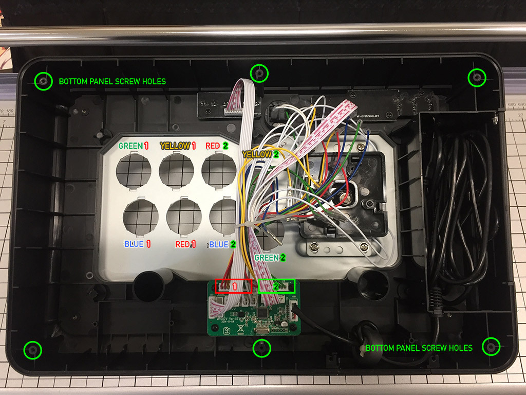
There are six screws located at the bottom of the Venom PS4 and Mayflash F500. The areas in green circle indicate where you will find the screws on the bottom panel. A Phillips head screwdriver is used to remove them.
You must remove the pushbuttons before lifting the clear, magnetic acrylic panel. The wiring duplicates colors across two connectors. Take note of the wire colors when detaching the quick disconnects, using the above photo as a guide, or taking your own photos of the wiring.
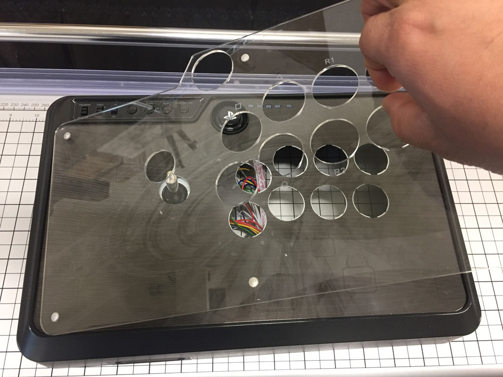
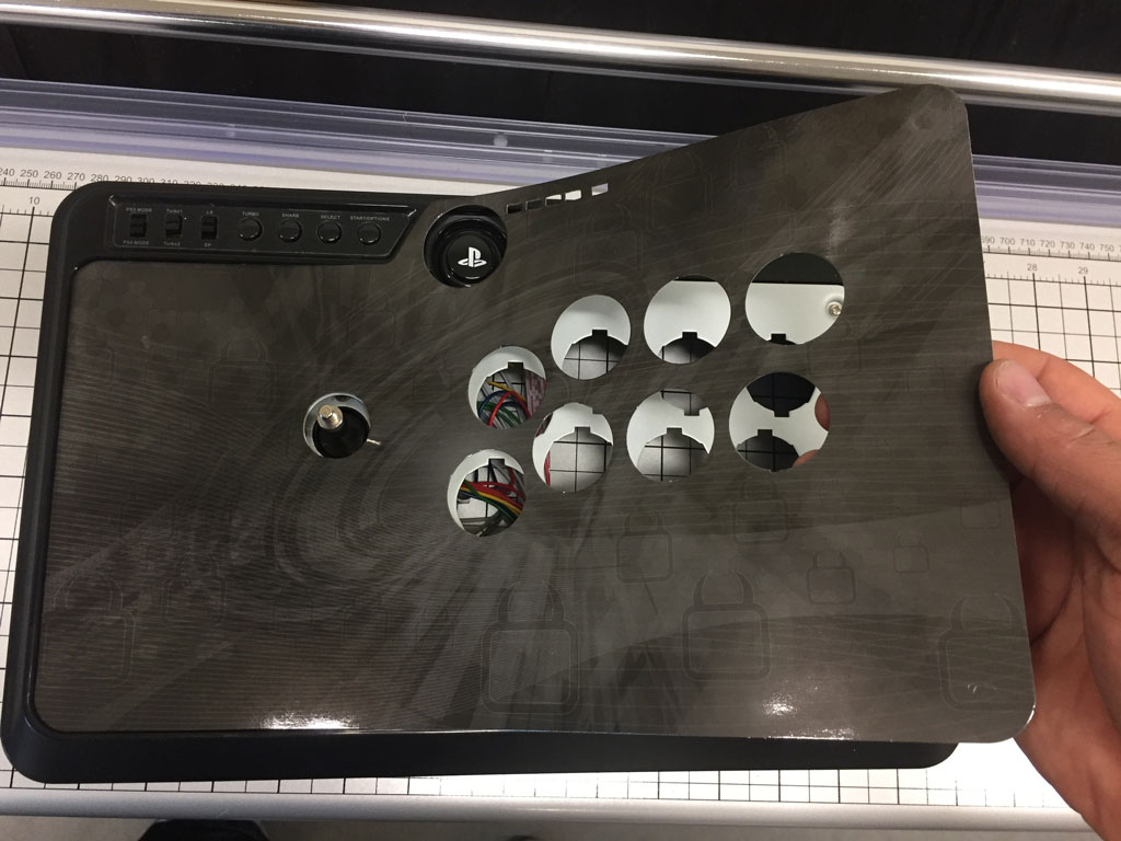
Once pushbuttons are removed, you can pull the acrylic panel upwards by grasping at the button holes. Eventually the magnetic force will give way, and the panel will lift up. With the acrylic panel removed, you can now remove the original artwork from the Fightstick, then replace with your custom artwork. Reverse all of the steps to install the acrylic panel and close the Fightstick. 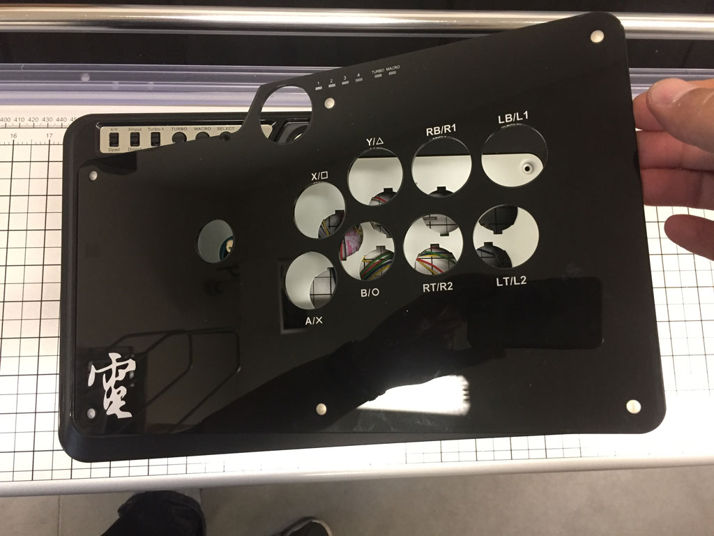
While the Mayflash PS3/XB360/PC and 8Bitdo FC30 Fightstick has a similar build as the Venom and Mayflash F500, they do not have a clear panel - the artwork is permanently attached to the panel. You will replace this acrylic panel with ours. As a reminder, this bundle is not compatible with the smaller Mayflash F300, Venom multi-console (featured red buttons instead of blue), or 8bitdo NS300 model. These models have their layout panel built into the Fightstick itself, therefore is not removable. 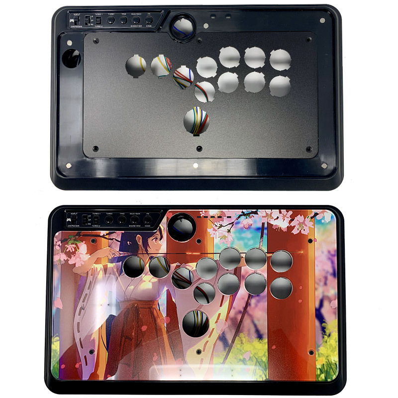
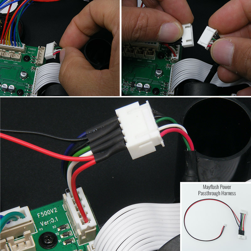
With the original acrylic panel removed, we now turn to the AFS Mayflash Stickless panel, the artwork, and plexi top. First, layer the panel in the open space left by the original panel. Next, add the artwork, and finally the acrylic panel top. Note that our acrylic panel will instead use the screw holes that remain after removing the original metal panel. With all of the layers applied (metal panel, artwork, acrylic panel), you can now install the six longer screws that we provide with your bundle. We flip the Mayflash Fightstick enclosure over to again reveal its wiring. We want to install the power passthrough harness. This harness will power the included SO.CD PCB by piggybacking the USB power.
- Next, you will disconnect the Mayflash's USB power cable connector. In the F500, this is located at the top left of the main control board.
- Now, attach the female end of the Mayflash Power Passthrough Harness to the male port on the main control board that you just removed the original UCB connector cable from.
- Finally, connect the female end of the USB cable connector to the Power Passthrough's male end.
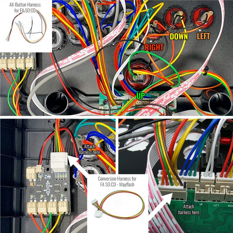
With the power passthrough cable installed, our next step is to connect the directional input wires from the the All-Button Harness for FA SO.CD to the SOCD PCB, then the Mayflash Conversion Harness to the Mayflash motherboard:
- First, attach the 2 pin female cable from the passthrough harness to the FA SO.CD's male VCC/GND connector. This brings USB power to the SO.CD. This connector is also keyed and can insert only one way. If you notice difficulty inserting the 2 pin female cable, it's likely that you have it upside down and need to flip.
- Next, wire the inputs from the All-Button Harness for FA SO.CD. The .110 quick terminal female end will attach to one of the male terminals of each directional button. Each wire color represents the input direction: ORANGE = LEFT; YELLOW = DOWN; RED = RIGHT; GREEN = UP.
- With the inputs attached, connect the ground daisy chain terminals to the second button terminal,
- Now, connect the ends of the All-Button Harness to the SOCD PCB. Start with the black ground wire of the harnesses' daisy chain. Notice the tinned edges of the harness wires. You will insert this into the "G" terminal block. You do not have to push forward hard or you risk damaging the terminal block. The terminal is designed to slide the tinned edge in and keep a secure grip. To release the grip and remove the wire, use a pen tip or similar and press down on the while pulling the wire out. Again, do not press too hard or you risk damaging the terminal block.
- While Mayflash original joystick uses fastener switches with connectors soldered to it, the company also has a 5-pin male port for standard Sanwa JLF like levers. Install the Mayflash conversion harness for FA SO.CD to this port. The conversion harness redirects the pinout from SO.CD to match the pinout on Mayflash's main board.
Now that our harnesses and SO.CD are connected inside, we want to test our inputs.
First, it is quite important that any harnesses used to connect parts of the main board to separate boards are attached properly. We've found that not having these connected can affect the accuracy of the input tests. Please use the full photo below to confirm the harnesses that you should have connected before starting the input test.
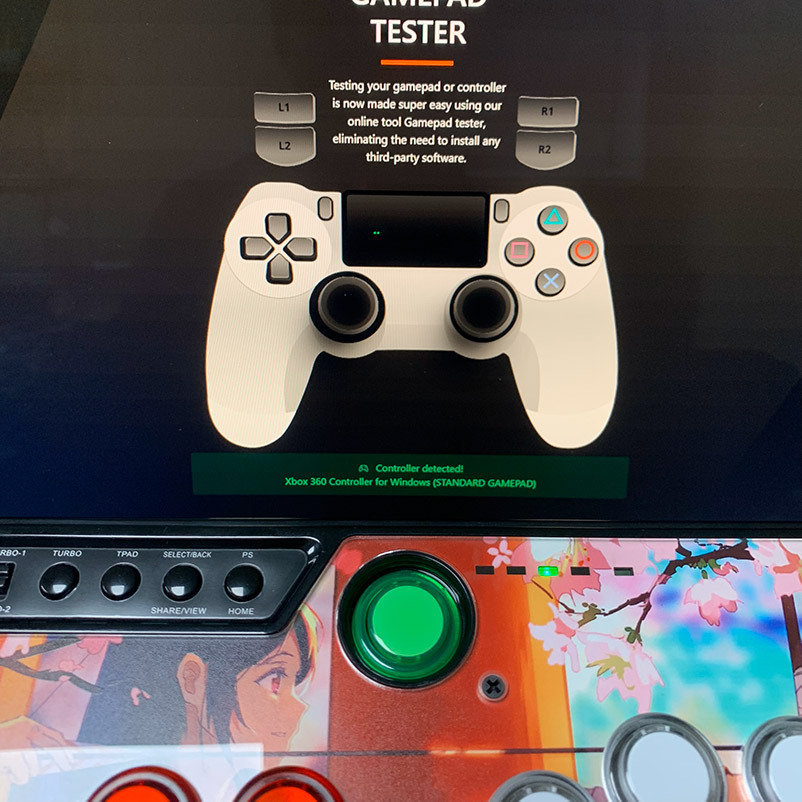
When you're ready, visit gamepadtester.net, a free online application that can confirm directions as input by the Fightstick to your computer, and by definition, to your console.
 Be sure to first flip your controller switch to "XINPUT" before plugging into your computer and performing the test.
 - First, test the directional buttons. Remember that the first 24mm directional button is LEFT, the second 24mm is DOWN, the third 24mm is RIGHT, and the fourth 30mm button is UP.
- Next, press the left and right input simultaneously. This should should show no activity on the gamepad screen. The FA SO.CD LEDs should also light up, displaying left + right LEDs on the input side, but no LEDs on the output side. The same should apply when pressing the up and down buttons at the same time. This lack of activity will represent "neutral", which is the CPT compliant SOCD cleaning method (L + R = N; U + D = N)
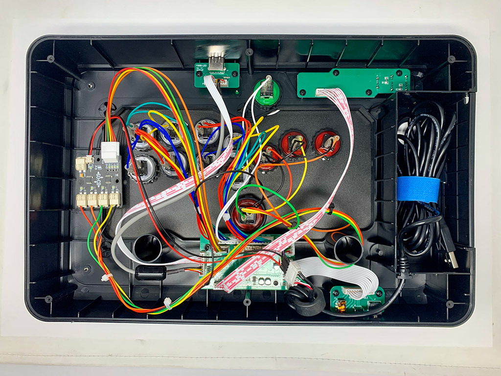
This photo can serve as a helpful guide for confirming that all wiring is intact and connected to their respective boards. Note the connectors to control panel, characterized by the ribbon cable with red striping. The other connector with magnetic shield ring attaches to the USB passthrough boards, commonly used with the Magicboots PS4/PS5/Xbox Series USB dongle. You'll want each of these connected before attempting to test the inputs via gamepadtester.net. To keep your wiring neat, you may want to purchase small zip-ties, zipping up the action button harnesses and snipping off the excess. 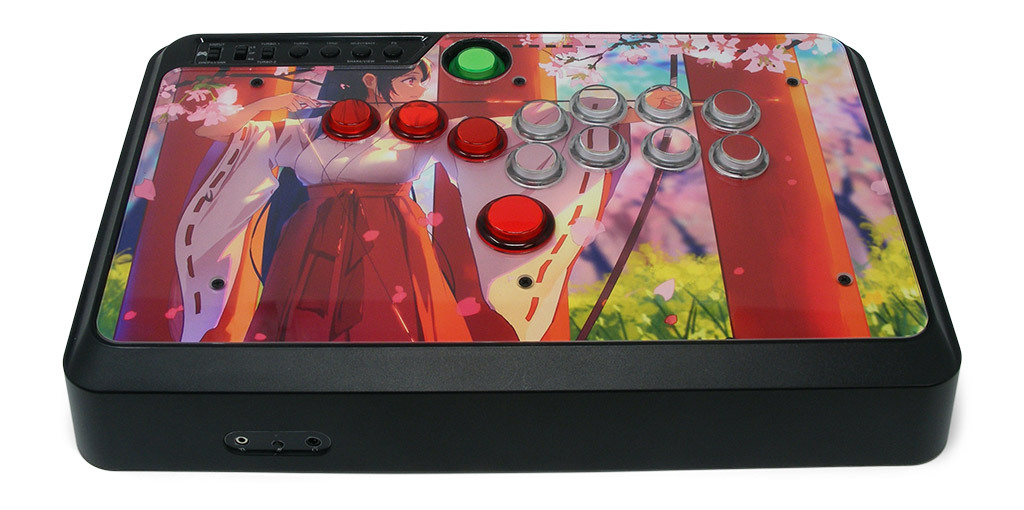
If you've made it this far, it's time to close up your new Stickless modded Mayflash F500. Flip the underside to reveal the 6 bottom screw holes, and re-attach the metal panel with the 6 bottom screws. Perform one final input test, and you're ready to start playing leverless on your favorite console (remember to play on PS4 or PS5 you will need Magicboots 1.2 or similar Mayflash USB dongle). Congratulations on your build! Options You have several options to personalize your control panel, such as button layout, removal of control panel or screws in some models, button label etching, and text etching.
REMOVING DEFAULT ELEMENTS | CUT BUTTON INSERTS
Layout Configuration
Each Fightstick has its own characteristics, with some sharing similar elements, such as the popular Vewlix button layout. We will specify what options are available for each Fightstick. Below are the most common button layout configurations:
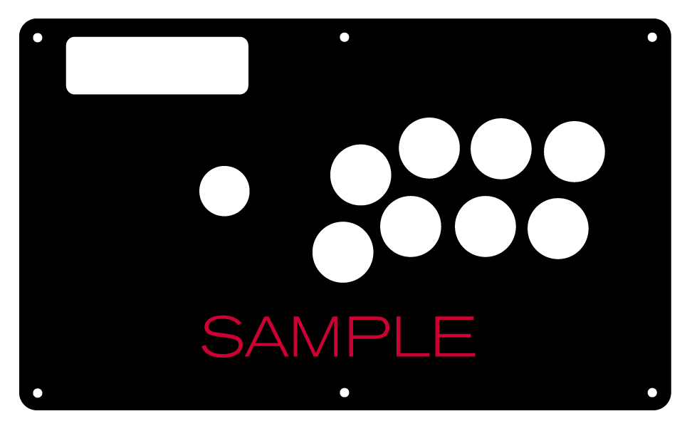
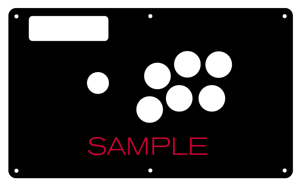
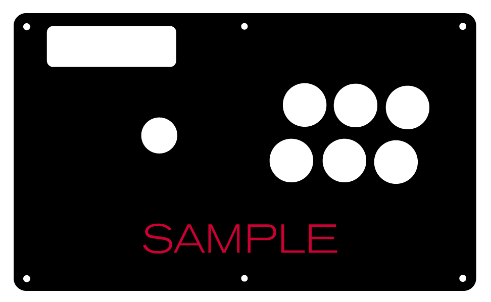
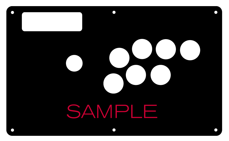 8 Button VewlixFirst 6 ButtonsLast 6 Buttons7 Button Vewlix
Removing Default Elements
Some Fightsticks, such as the popular MadCatz TE, offer additional personalization options by removing default elements such as control panel, start button, or screws. Cut options are defaulted to their authentic counterpart, displayed as [YES (default)] in the options list. For example, a MadCatz TE, the default configuration is to have the turbo/guide portion of the control panel cut, so that the control panel can fit properly. You have the option to select [NO] to prevent cutting these areas.
![Cut Control Panel? [NO]](http://support.focusattack.com/attachments/token/ioB7e1jzIXfxKdM8KJPKKzvKD/?name=sample-8button-noturbo.png)
![Cut Start Buttons [NO]](http://support.focusattack.com/attachments/token/SWbsx5sVHYupnBQ5iuZH1S2HK/?name=sample-nostart.png)
![Cut Middle and/or Bottom Screws? [NO]](http://support.focusattack.com/attachments/token/QzFj5pc5cNNHkOKrzlEMcc0I4/?name=sample-8button-nomiddlescrew.png) Cut Control Panel? [NO]Cut Start Button? [NO]Cut Middle and/or Bottom Screws? [NO]
Cut Control Panel? [NO]Cut Start Button? [NO]Cut Middle and/or Bottom Screws? [NO]
Cut Control Panel? [NO] - If you own a MadCatz TE, and installed a PS360+, you may no longer need the Turbo/Guide area of the control panel, located at top left. This option allows you to remove the Turbo/Guide portion. Please note that you MUST remove the actual control panel on the TE by unscrewing it before applying the plexi, or you risk damaging the plexi. Also, please make certain to select this option if you are also choosing to have artwork printed, or the plexi and artwork won't match.
Cut Start Button? [NO] - On some joysticks - such as the Qanba Q4 - the start button is directly on the panel. You can select to have this removed. You can also select this should you desire a panel similar to the Eightarc Fusion or Synthesis series Fightstick, as the start button is moved elsewhere. Again, this option is available on specific joysticks.
Cut Middle and/or Bottom Screws? [NO] - Selecting "no" on this option allows you to remove the middle top and bottom screw holes on specific joysticks, either for a cleaner appearance or to avoid rubbing your wrist against the screw. Please reconsider this option if you intend to have a full panel etch on your plexi, as etching physically changes portions of the plexi due to heat. In this case, it is best to leave the screw holes in place in order to keep the panel securely positioned.
Cut Button Inserts

Pushbutton manufacturers such as Sanwa, Seimitsu, Crown and GamerFinger have each produced specific models with a clear or translucent plastic cap and flat plunger. These are often used to display a graphical insert, allowing you to enhance the button's appearance. That said, each button manufacturer has designed the artwork cap with a different diameter than their competitors. For example, GamerFinger's artwork cap has a diameter that is slightly larger than Seimitsu or Sanwa. An insert cut for a Sanwa artwork cap will fit loosely when inserted into the GamerFinger artwork cap. This is an undesirable result that can produce a white or colored ring around the insert.
Now, you can choose the button insert cut to match the pushbutton you intend to use. This allows the insert to fit snugly within the cap.
Brands and Model with Artwork Caps
- Sanwa - OBSC (30mm) | OBSC (24mm)
- Seimitsu - PS-14-GN-C (30mm) | PS-14-DN-C (24mm) | PS-14-K (30mm) | PS-14-KN (30mm) | PS-14-DN-K (24mm)
- Seimitsu - ALUTIMO SSPS MX 24mm and 30mm
- Crown - SDB-201-C, SDB-202 MX (30mm) | SDB-202-MX (24mm)
- Qanba - GRAVITY 24 and 30mm
- GamerFinger - HBFS30 (30mm) |HBFS24 (24mm)
In some instances, a button brand or model does not have a 24mm equivalent with art cap. In this case, we will cut to the default size of Sanwa 24mm insert.Please note that if you later intend to purchase a different button, you may need to get new button inserts or new artwork. If you are uncertain which button you may choose, Sanwa is chosen by default.
Button Cut for Qanba Q2 Glow
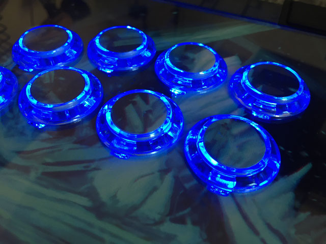 Qanba Crystal and Q2 Glow feature buttons manufactured by Qanba. These buttons have a smaller cap diameter, and thus require a smaller artwork insert. If you plan to keep the Qanba Crystal or Q2 Glow buttons installed when updating your artwork, please choose the option "Crystal/Q2 Glow".
24 vs 30mm
When processing orders, a frequent mistake we found among new players is choosing the wrong size for action buttons, such as punch and kick.
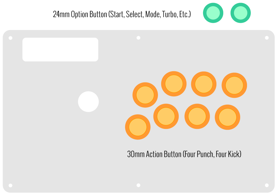
Within the fighting game genre, Japanese arcade buttons commonly consist of two diameter sizes: 24 millimeter and 30 milllimeter (mm). In most configurations, 30mm represents your action button. These are front facing, appearing most prominent on your Fightstick control panel. Option button, such as "Start", "Select", or more recently "Option", "Touch", or "Share" are usually 24mm.
UPDATE: Owners of Neo Geo AES Joysticks will need 24mm pushbuttons instead of 30mm (Thanks SRK's DEZALB)
Below is a visual representation of a common Fightstick control panel. Throughout this article, we will mark 24mm in green, and 30mm in Orange.
Checking the Proper Size
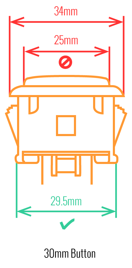 Another way that players can misinterpret the pushbutton size is by measuring the pushbutton plunger. Have a look at the diagram at right.
The plunger - the part that you press down to represent an input - is 25mm or a bit smaller in most 30mm pushbuttons. Often this leads to the conclusion that one needs a 24mm button and not 30mm.
Similarly measuring the button rim can lead to confusion, as it is intentionally larger than the button hole it is placed in. You don't want to use these measurements. Instead, review the button housing diameter, or the hole the button will be placed in. You can do this with a caliper - a digital caliper is often quite helpful for this and other arcade-related projects.
Control Panel Configuration
Most Fightsticks from MadCatz, Hori, Qanba, and similar will use these two sizes. How the buttons are used will depend on the model joystick that you own. Over time, we'll provide example configurations for specific popular Fightstick models and arcade cabinets using the color key for 24mm (green) and 30mm (orange). We'll also expand the key for future models if another size is introduced, and we offer for sale.
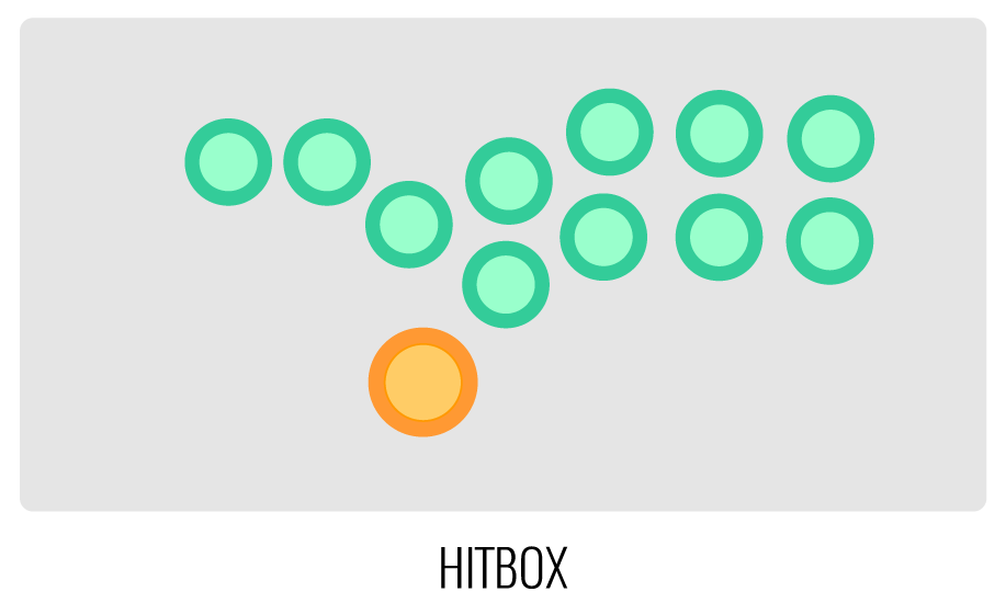
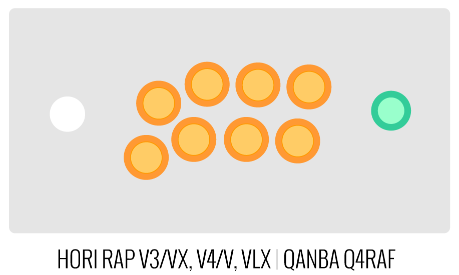
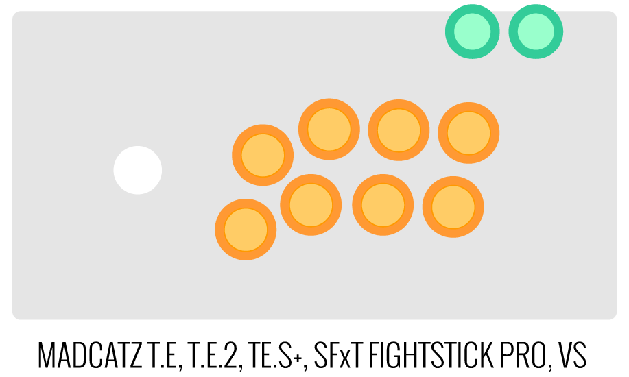
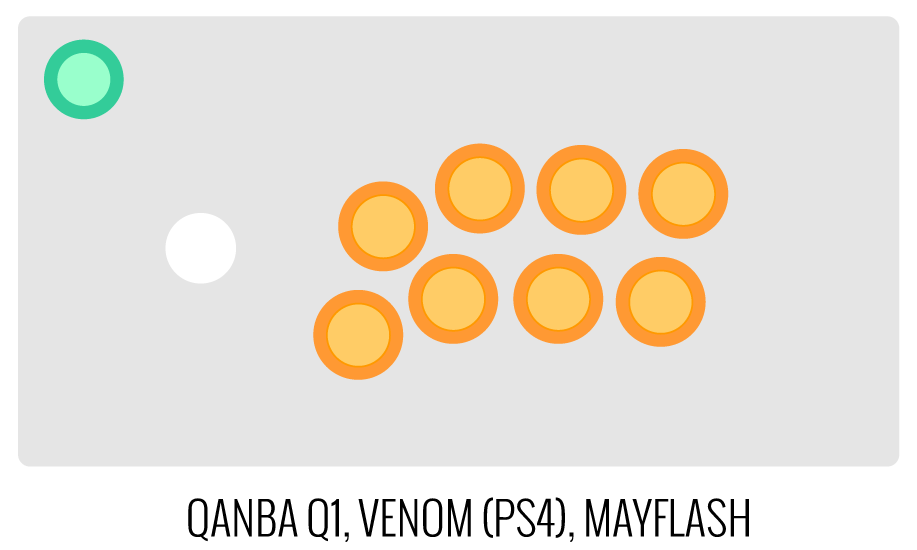
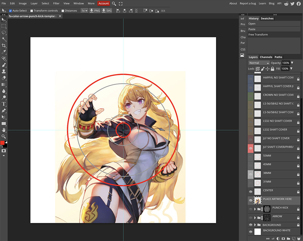
Image Edit If you would like to use a free, online Photoshop-like app to check out whether your artwork will work with a layout we offer, I highly recommend Photopea
 This amazing app works with our PSD templates and is a great way to preview your artwork or create new art files. It also exports to PSD, which is the format we recommend for submitting artwork.
Support New to FA Plexworks?
Click the "Options" tab for a detailed explanation of each customization option available to you. Using a mobile device? Click here to scroll to the descriptions.
Artwork templates
We offer a photoshop template for each custom artwork or custom plexi etch. Click the "Description" tab (or scroll up if on mobile device) to display the template and download. You can also click here to access our repository and download artwork and etch templates (in Photoshop PSD format) for your desired model and others.
Important: Using templates outside of the ones we provide may produce unwanted output. We are not responsible for output generated from unsupported templates. More information here.
Warranty and Support for FA Plexworks Custom Order
Custom orders cannot be returned for refund, or exchanged for another custom order. Orders damaged upon arrival are subject to special terms within our return policy. Please see our FA Plexworks FAQ for more information about our Plexworks return policy and related Q&A.
If you have not used our Plexworks custom services before, we recommend that you visit our support section for updated information, helpful tips, and resources to get the best output.
Some useful sections to review before making your purchase (will open in new browser window or tab):
- Learn about our Custom Job Tracker to keep tabs on your custom order while staff processes it from start to finish.
- Save time getting answers by visiting our FAQ.
- Learn more about the personalization options available to you.
- Hire a skilled artist from the Fightstick Artists Network to visualize your idea.
- Handling the artwork yourself? Review our requirements and get tips to optimize your laser etch or artwork submission.
- Learn about additional products and services we offer under FA Plexworks.
- Project L Official Artwork: Do not submit the PNG samples. Instead, please download the zipped Photoshop PSD version, unzip the file and integrate them into our artwork templates
-
Product Reviews
-
Product Videos
-
 FA Plexworks Custom Fightstick Artwork ServicesThis video explains the many options available to you when cho...
FA Plexworks Custom Fightstick Artwork Services
This video explains the many options available to you when choosing custom FA Plexworks services at focusattack.com. We also cover important tips and references for properly uploading artwork when placing an order. Visit https://www.focusattack.com/customize/ to place an order for custom Fightstick artwork, a replacement acrylic top, or even laser etched design on acrylic. For additional information about FA Plexworks, download templates, and additional tips on how to submit artwork, visit our support portal http://bit.ly/fa-plexworks-support Big thanks to Naota for his pro-tier production! ** Artwork pictures are sample illustrations. All printed artwork is submitted by the user, and not sold directly on the website. -
-
Find Similar Products by Category


