- Category
- What's New?
- FightSticks/Pads
- Joysticks
- Pushbuttons
- Spare Parts & Tools
- Hardware & PCB
- Electrical
- Customize
- Merchandise
- Pre-Order
- Sales & Clearance
- Brand
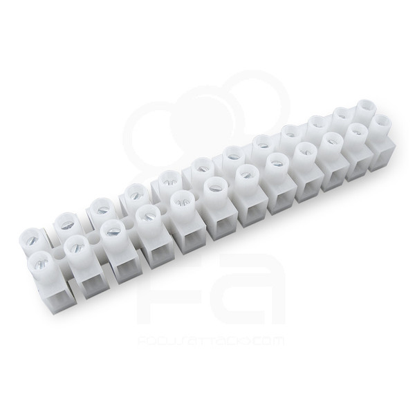
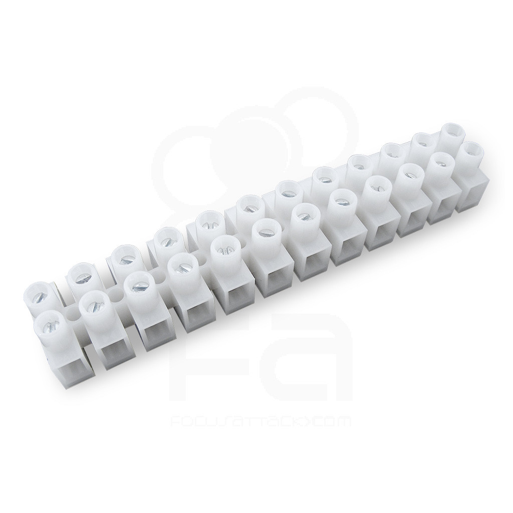
Philmore 12 Terminal Euro Style 18-20 AWG Barrier Strip
Sorry but this item is currently unavailable.
Please check back at a later stage.
-
Product Description
Terminal blocks are a common component found in electrical equpment, serving two main purposes:
- You can connect two wires together without needing to splice or physically joining the wires. Two or more wires can also fit together into a single screw terminal.
- Allows you to distribute power from a single source to multiple devices.
Barrier strips - by definition - have a short metal strips which are separated by an insulated "barrier". Each strip has a pair of screws; each screw connects to a conductor on each end of the strip.Euro style barrier strips can be cut to size simply by using a wire cutter, allowing you to create multiple blocks of fewer terminals if needed. Screw terminals keep the wire secure for greater conductivity.
Specifications
- Amps: 6
- Volts: 400V
- Length: 95.8 mm (3.77 inches)
- Width: 16.3 mm (.64 inches)
- Screw Size: 2.6mm x 5mm
- Wire Size: 18-20 AWG (higher AWG is possible to connect)
Use Scenario Dual and Triple Console Mods for FightSticks
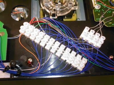
Professional modder Clayton Knight (aka Phreakmods) used barrier strips to connect a Xbox 360 and Playstation gamepad to a PS3 Tournament Edition Fightstick and Toodles Imp. While he states that the high AWG wire he used has a greater propensity to snap under screw terminals, the use of euro style blocks enable much easier swapping of the PSX pad if it ever failed.
Full details are available here.

-
Product Reviews
-
Save some time by NOT soldering when you don't have to!
The best time to use a terminal barrier strip is when you want to be able to remove wires but not have to go through the process of cutting wiring again or desoldering it.
Soldering is a pain for a lot of people and it's a potentially dangerous proposition. You have to be on constant alert not to burn yourself or things you DON'T want to damage, and you have to be wary of the soldering iron itself and lay it somewhere it doesn't get tripped or fall and burn things.
I've used barrier strips for PCBs where I'm trying to recycle the existing directional signal wires. It can be a pain to desolder wiring at certain small points on a PCB -- usually the directional wires are a pain to remove on certain PCB's like Tekken 5/Arcana Heart 2. It may safer to "recycle" it and run it through a terminal to join with a new joystick harness. The terminal saves you from potentially burning the PCB, lifting trace, and also having to remember the order those harness wires were soldered onto that PCB!
Yeah, nowadays, most people don't deal with the Hori licensed HRAP PCB's like the PS2-era PCB's where the stock Hori buttons (NOT Hayabusa or Kuro, those came later and are MUCH better buttons!!!) were soldered directly onto the board and the joystick harnesses had ultra short wiring.
George C on Nov 24th 2021 -
These are PERFECTLY SAFE for most situations where you don't want to solder wiring
The electricity (amperage, voltage) running through joystick signal lines is pretty low.
These terminals are rated for wiring that's THICKER and runs HIGHER electrical output through them than the 22-24AWG wires joysticks use.
I've used terminals similar to these that I bought from Radio Shack (remember when those used to exist?!?) and they did the job fine in helping to extend connections without needing to solder in wiring.
Believe me -- I've NEVER been shocked or burned by joystick wiring but then again I NEVER did any electrical work with the joystick plugged into an active computer or console! LOL
Here's the situation where I used a terminal strip (European like the one in the picture):
I've owned Hori "licensed HRAP joysticks" (Tekken 5 10th Anniversary/US edition, Arcana Heart 2) where the original JLF connector had ultra-short wiring soldered onto the Hori PCB -- you know, those BRICK-SIZED PCB's that had the Hori pushbuttons directly soldered onto the PCB? Most of us that worked with these are familiar with them from the Tekken 5/10th Anniversary joystick and the Arcana Heart 2 joystick had a similar PCB setup.
Anyway, I felt very confident desoldering the pushbuttons since those points were HUGE in comparison to the JLF wiring connector point.
I left the original JLF wiring soldered into the PCB -- It's thinner than the wiring the actual JLF wire harness uses, btw. Your options then were to solder a new JLF harness (making sure to match the wires PROPERLY by signal line; usually red to red, yellow to yellow, by color) directly onto the original PCB directional signal lines OR use a terminal strip/barrier to connect the two wires. On 3-5 occasions, I chose to use terminal strips to connect and thereby extend the length of the joystick lever connection.
(NOTE: It doesn't hurt to wrap bundles of copper wire from spare 22-24 AWG electrical wiring around the end of the PCB directional signal wires to make them more substantial before you plug them into the terminal. Hori used VERY thin wire on its licensed joystick PCB's for the joystick harness connection and sometimes that wire may not "connect"/touch the terminal strip metal properly to conduct electricity; I'd wrap copper wire strands around the old PCB directional wires at the exposed ends and TIN them with a soldering iron personally to triply make sure these wires conduct signal electricity well.)
By using a terminal strip/barrier to extend the length of the joystick lever harness wiring leading out from the PCB, it makes it easier to service the inside of an HRAP 1-3 style joystick. You no longer have to worry about snapping wire off the PCB/breaking old soldering points on the PCB when you life up the faceplate after unfastening it.
The Arcana Heart 2 joystick I own has REALLY short length of JLF connector wiring so I used the terminal strip and an used JLF harness wire to make that situation safer. I take my HRAP 2-3 faceplates off on occasion to play with the spring tension in the joystick levers or even swap levers to test new parts... Unknown on Dec 15th 2020 -
Philmore 12 Terminal Euro Style 18-20 AWG Barrier Strip
The Philmore 12 Terminal Euro Style 18-20 AWG Barrier Strip is exactly what I was looking for. Good quality producvt Tom I on Dec 3rd 2018
-
-
Product Videos
-
 Philmore 12 Terminal Euro Style 18-20 AWG Barrier StripIn this video, we explain how the Philmore strip is utilized t...
Philmore 12 Terminal Euro Style 18-20 AWG Barrier Strip
In this video, we explain how the Philmore strip is utilized to dual mod an Akishop PS360+ with Hori Fighting Commander 4 for PS4. Modding performed by Yury AKA SRK-Yenjoi and Joey W from focusattack.com. Look for more tips to come. -
-
Find Similar Products by Category


